ASSALAMUALAIKUM :D
FINAL COUNTDOWN!
Finally,the day has come.
Alhamdulillah for that day.
Thanks to Sir Saiful ,as our supervisor.
Alhamdulillah for everything :D
So that all from me And hakim ....
WASSALAM

The Wireless Mailbox Using Arduino is a simple device that is perfect for anyone who hates continuously checking the mail box only to find that the mail hasn't been delivered yet. By sending a wireless signal from the mailbox to a receiver placed conveniently anywhere in the home, you will know exactly when your mail has come and finally put an end to the inconvenience of the mailbox.
25 December 2013
19 December 2013
WEEK 12 & 13 (PREPARATION FYP PRESENTATION )
So far for this week we are just do it the preparation ....
like search something that we can use for our prom when we are do it the preparation and also in this two week we still trying and running our project , we still trying tidy up or refined our circuit and mail box because the mailbox we make it the mail by our self and also doit the poster

 FIGURE 12.2 the mailbox that we are make it by our self
like search something that we can use for our prom when we are do it the preparation and also in this two week we still trying and running our project , we still trying tidy up or refined our circuit and mail box because the mailbox we make it the mail by our self and also doit the poster

FIGURE 12.1 Our poster

14 December 2013
WEEK 11 ( TESTING THE PROJECT )
Okey , this week is a last one we are update our project ...
and as stated on the title, this week we are just testing and running our project before we take our project to advisor.
So this is a our fully project with fully attacig the ofircui to the mail box
and as stated on the title, this week we are just testing and running our project before we take our project to advisor.
So this is a our fully project with fully attacig the ofircui to the mail box

so firstly we can show how our project will be function it ...


30 November 2013
WEEK 8 , 9 , 10 (PROGRAMMED THE MICRO CONTROLLER[ARDUINO UNO] )
so for this week also we are do it program the arduino for our project .
This is just for review to help our friend to use manually this microcontroller .
Burning the Bootloader
If you have a new ATmega328 (or ATmega168), you'll need to burn the bootloader onto it. You can do this using an Arduino board as an in-system program (ISP). If the microcontroller already has the bootloader on it (e.g. because you took it out of an Arduino board or ordered an already-bootloadedATmega), you can skip this section.
To burn the bootloader, follow these steps:
- Upload the ArduinoISP sketch onto your Arduino board. (You'll need to select the board and serial port from the Tools menu that correspond to your board.)
- Wire up the Arduino board and microcontroller as shown in the diagram to the right.
- Select "Arduino Duemilanove or Nano w/ ATmega328" from the Tools > Board menu. (Or "ATmega328 on a breadboard (8 MHz internal clock)" if using the minimal configuration described below.)
- Run Tools > Burn Bootloader > w/ Arduino as ISP.
You should only need to burn the bootloader once. After you've done so, you can remove the jumper wires connected to pins 10, 11, 12, and 13 of the Arduino board.

<==== Using an Arduino board to burn the bootloader onto an ATmega on a breadboard.
Once your ATmega328p has the Arduino bootloader on it, you can upload programs to it using the USB-to-serial convertor (FTDI chip) on an Arduino board. To do, you remove the microcontroller from the Arduino board so the FTDI chip can talk to the microcontroller on the breadboard instead. The diagram at right shows how to connect the RX and TX lines from the Arduino board to the ATmega on the breadboard. To program the microcontroller, select "Arduino Duemilanove or Nano w/ ATmega328" from the the Tools > Board menu (or "ATmega328 on a breadboard (8 MHz internal clock)" if you're using the minimal configuration described below). Then upload as usual.
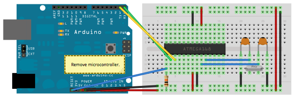
Uploading sketches to an on a
breadboard. Remember to remove ======>
the microcontroller from the
Arduino board!
Minimal Circuit (Eliminating the External Clock)
If you don't have the extra 16 MHz crystal and 18-22 picofarad capacitors used in the above examples, you can configure the ATmega328 to use its internal 8 MHz RC oscillator as a clock source instead. (You don't really need the 10K pullup resistor on the reset pin either, so we remove it to get a truly minimal configuration.)
You'll need to install support for an additional hardware configuration:
- Download this hardware configuration archive: Breadboard.zip
- Create a "hardware" sub-folder in your Arduino sketchbook folder (whose location you can find in the Arduino preferences dialog). If you've previously installed support for additional hardware configuration, you may already have a "hardware" folder in your sketchbook.
- Move the "breadboard" folder from the zip archive to the "hardware" sub-folder of your Arduino sketchbook.
- Restart the Arduino software.
- You should see "ATmega328 on a breadboard (8 MHz internal clock)" in the Tools > Board menu.
Once you've done this, you can burn the bootloader and upload programs onto your ATmega328 as described above. Be sure to select "ATmega328 on a breadboard (8 MHz internal clock)" when burning the bootloader. (If you select the wrong item and configure the microcontroller to use an external clock, it won't work unless you connect one.)

<====== Using an Arduino board to burn the bootloader onto an ATmega on a breadboard (w/o an external clock).

Uploading sketches to an ATmega on a breadboard ==>
Getting Rid of the Arduino Board
Once you've programmed the ATmega on the breadboard, you can eliminate the Arduino. To do so, you'll need to provide an alternative power supply for the microcontroller .so this is just review for help a reader who want to know how to use that from Arduino to a Microcontroller on a Breadboard and based from our project we are not use this technique because we are strightly using arduino uno for our based in using microcontroller . so now we are teach the beginner like we how to use arduino .
// just review and reminder again

Hardware Setup
- Install USB to UART driver.
- Connect Arduino UNO to computer via USBcable.
- Open Arduino IDE.
- Choose your board under Tools-> Board->Arduino UNO.
- Choose COM port under Tools-> Serial Port-> COM ? (Check from Device Manager).
Software Setup
- Open Blink Example, File-> Examples->1.Basic-> Blink

1st Compile and Load
- Click Compile
- There should be no error as it is example code.
- Click Upload
- Rx & Tx LEDs on Arduino will blink, and“Done uploading” will appear on IDE.
- After a few seconds, the LED (pin 13) onArduino will start blinking ~ 0.5Hz.
Modifying the code
- Save as another file, maybe as “my_Blink”
- Modify the blinking rate, become 1Hz, 2Hz or faster.

15 November 2013
WEEK 6 , 7 & 8 ( ASSEMBLE ALL COMPONENT )
There was so much buzy for the did this week due to our busy lifetime with classes and assignments need to be done and submitted. Also this week we were just doing the combination between software and hardware. And we also keep on trying the circuit in case it did not function . So firstly we do it we are do it is the PCB DESIGN .A PCB is a thin board made of fiberglass, composite epoxy, or other laminate material. Conductive pathways are etched or printed onto board, connecting different components on the PCB, such as transistors, resistors and integrated circuits. We have design the transmitter and receiver circuit using Fritzing software. So from the circuit above, we start to understand the flow from one stage to another stage. We took a week to complete this circuit. Referring to the circuit picture, we have successfully installed all the components on breadboard.
RECEIVE CIRCUIT


TRANSMITTER CIRCUIT


For the second construct the circuit with refer the schematic diagram like we are doing from the PCB DESIGN but now we are just only construct the circuit using the breadboard

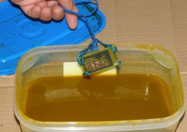
and also what we do it in this week is we are doing etching that etching is the process of using strong acid to cut into the unprotected parts of a metal surface to create a design in print-making in the metal.
Now that you're itching to etch . . .
After you go through all the preliminaries in the preceding sections, you get to actually etch your printed circuit board.
Follow these steps to etch the board:
1. Pour the etchant into the plastic tray carefully, avoiding spills and splashes.

Pour enough etchant to create a pool at least 1/8-inch thick, preferably 1/4-inch thick.
2. Dunk the board into the tray and continually rock it back and forth.

3. Keep the board in the soup for 10 to 30 minutes
(depending on the type and strength of the etchant) or until the etchant
has removed all the excess copper. Keep that tray a-rockin — but
gently!

4. Use the plastic or wooden tongs to lift the board out of the tray from time to time to check progress.

The enchant removes the copper, starting from the edges and areas
close to the resist. Large, open areas of copper can be stubborn and
take 2 to 3 times as long to etch completely. You may want to agitate
those areas of the copper that don't respond as quickly to the enchant.
However, be sure that you don't over-agitate because you can undercut the
copper under the resist. Undercutting happens when enchant oozes under the resist and attacks the copper that you don't want to remove. After that we are also transfer the circuit from breadboard to the strip board .
 that's all for this 3 week....
RECEIVE CIRCUIT


TRANSMITTER CIRCUIT
For the second construct the circuit with refer the schematic diagram like we are doing from the PCB DESIGN but now we are just only construct the circuit using the breadboard
and also what we do it in this week is we are doing etching that etching is the process of using strong acid to cut into the unprotected parts of a metal surface to create a design in print-making in the metal.
Now that you're itching to etch . . .
After you go through all the preliminaries in the preceding sections, you get to actually etch your printed circuit board.
Follow these steps to etch the board:
1. Pour the etchant into the plastic tray carefully, avoiding spills and splashes.

Pour enough etchant to create a pool at least 1/8-inch thick, preferably 1/4-inch thick.
2. Dunk the board into the tray and continually rock it back and forth.
3. Keep the board in the soup for 10 to 30 minutes
(depending on the type and strength of the etchant) or until the etchant
has removed all the excess copper. Keep that tray a-rockin — but
gently!
4. Use the plastic or wooden tongs to lift the board out of the tray from time to time to check progress.

The enchant removes the copper, starting from the edges and areas
close to the resist. Large, open areas of copper can be stubborn and
take 2 to 3 times as long to etch completely. You may want to agitate
those areas of the copper that don't respond as quickly to the enchant.
However, be sure that you don't over-agitate because you can undercut the
copper under the resist. Undercutting happens when enchant oozes under the resist and attacks the copper that you don't want to remove. After that we are also transfer the circuit from breadboard to the strip board .
31 October 2013
WEEK 4 & 5 ( RESEARCH ABOUT SENSOR AND LIST ALL THE COMPONENT USUAL )
Those of you is it know what is a sensor
Sensors
come in all shapes and sizes, from the motion detectors that signal
lights to go on when we enter a room to Geiger counters that detect
radiation loss. They are used in commercial, industrial and personal
applications, whether to tell us when we have a fever or to regulate
conveyor systems in a factory. We even contain a number of biological
sensors that regulate chemical balances within our bodies, or cause us
to react to different stimulate.
Even in the manufacturing
realm, the term sensor covers such a wide variety of applications and
devices that it is almost impossible to define. Nonetheless, regardless
of the industry, sensors are used to alert a person or system; sometimes
this is in order to generate a new function, such as switching off a
furnace, while in other instances it is to signal a problem. The
majority of sensors, however, are meant to help regulate and control
existing operations. Various speed and position sensors, for instance,
assist in automotive engine management. Adjustable linear, null balance
and output current sensors monitor AC or DC current for different
electrical or industrial systems. Proximity sensors assist in aircraft
and marine applications, among others.
Other sensor
types include photoelectric sensors, which detect objects with light and
have exceptional range; liquid level sensors and debris monitors, which
can be used on fixed wing and rotary aircrafts; temperature and
pressure meters, which factor into an immense range of industrial,
commercial, medical and processing systems; and electrochemical sensors,
such as amperometric and coulometric sensors, which measure various
biological functions. From the places we visit to our means of
transportation, we are surrounded by sensors and systems that rely on
sensors, as well as goods that could not exist without them.
Sensors
play even more direct roles in our everyday lives. Thermometers and
barometers tell us the weather, oil and fuel gages keep our cars
running, and proximity sensors turn on and off our outdoor lights. Of
course, direct applications do not stop there. Automated doors,
elevators, ovens and refrigerators all incorporate sensors into their
designs, making sure our pathways stay open, our food stays fresh, and
our appliances remain dependable.,


Main Component/Part Used In This Project
Arduino Uno - Microcontroller
Arduino
is an amazing tool for physical computing. It is an open source microcontroller
board, plus a free software development environment. The usage of arduino is to
make cool interactive objects that can sense inputs from switches, sensors, and
computers and then control motors, lights, and other physical outputs in the
real world.
The Arduino Uno is compatible with
all current shields and code, and comes assembled. It’s simple to use by just
connected it to a computer with a USB cable or power it with AC-to-DC adapter
or battery.
In this project, we use Arduino Uno as our microcontroller. Since our project
consists of receiver and transmitter, we have to use two Arduino Uno for both
circuit as the microcontroller to control all the other part that attached to
the circuit. This Arduino Uno can simply be control by a code that can be
written using the Arduino software.

-
 Pin Out
RF Link Receiver and Transmitter
This is the 315MHz transmitter and receiver that will work with the RF Links at 315MHz at either baud rate. This wireless data is easy to use and it also the lowest cost RF link that we have ever see. The RF link transmitter is use to transmit position data, temperature data, even current program register values wirelessly to the RF link receiver. These modules have up to 500 feet range in open space. The transmitter and receiver operates from 2-12V. The range will be greater if the voltage is higher.
We have looking forward these modules extensively and have been very impressed with their ease of use and direct interface to an MCU. The theory of operation is very simple. What the transmitter 'sees' on its data pin is what the receiver outputs on its data pin.
This is an ASK transmitter module with an output of up to 8mW depending on power supply voltage. The transmitter is based on SAW resonator and accepts digital inputs, can operate from 2 to 12 Volts-DC, and makes building RF enabled products very easy.

IR Sensor
IR Sensors work by using a specific light sensor to detect a select light wavelength in the Infra-Red (IR) spectrum. By using an LED which produces light at the same wavelength as what the sensor is looking for, you can look at the intensity of the received light. When an object is close to the sensor, the light from the LED bounces off the object and into the light sensor. This results in a large jump in the intensity, which we already know can be detected using a threshold.
Depiction of the operation of an IR Sensor
Detecting Brightness
Since the sensor works by looking for reflected light, it is possible to have a sensor that can return the value of the reflected light. This type of sensor can then be used to measure how "bright" the object is. This is useful for tasks like line tracking.

IR Sensor
Alarm Buzzer
For alarm buzzer, we use speaker as it can produce a louder sound. This speaker will produce an alarm sound that can alert the people in the house when there is a letter in their mailbox. This 30mm diameter speaker is encased in plastic and will handle about 100mW of power.
 LLCD Display Description
After our advisor approved with our explanation on the circuit testing we decided to buy our component at our best electric and electronic market the Jalan Pasar, pudu.


Subscribe to:
Comments
(
Atom
)